Gaya Ships Packages Optimization - Draft
Introduction
This document outlines the optimization strategies employed for Gaya ship packages, focusing on reducing package size and improving in-game performance. The optimizations target model complexity, texture management, and level of detail (LOD) implementation. By streamlining the asset pipeline, we aim to deliver a more efficient and performant experience.
Purposes
The primary purposes of this optimization effort are:
- Reduce memory footprint: Minimizing the size of ship packages to improve loading times and reduce overall memory usage.
- Enhance runtime performance: Optimizing models and LODs to improve frame rates and reduce rendering overhead.
- Simplify asset management: Streamlining the Blender file structure and asset organization for easier iteration and maintenance.
- Improve asset reusability: Enabling the creation of multiple ship variations with minimal additional assets.
Optimization Components
LOD Fixing
- Independent LODs: The main ship model is divided into smaller, independent sub-models. This allows for granular control over LOD transitions, ensuring that only necessary details are rendered at any given distance.
- Instance Optimization: Redundant or "killed" instances of objects are removed or replaced with efficient alternatives, reducing draw calls and memory usage.
Reduce Package Size
- Asset Reuse: The same base objects are reused across different ship variations, minimizing the number of unique models required.
Simplify Blender File
- Clean Geometry: Unnecessary geometry and "killed" instances are removed, reducing the overall complexity of the Blender file.
- External Texture Management: Embedded textures are removed, and only essential objects are retained in the Blender file, resulting in a significantly smaller file size.
Method
Dev Package
- Model Attachments: The "MODEL ATTACHMENTS" method is utilized to create a modular ship structure. This involves breaking the ship into smaller pieces, creating a new model for each piece, and attaching them to a base GLTF file. This approach allows for flexible variation creation with fewer unique models.
- Base GLTF Structure: The base GLTF file contains two empty nodes that serve as attachment points for ship components.
- The first node, named "[ship_name]" (e.g., "Microsoft_Ships_LucyBorchard"), is used for attaching the standard ship components.
- The second node, named "[ship_name]_Sink" (e.g., "Microsoft_Ships_LucyBorchard_Sink"), is used for attaching the sunken ship variations.
Note
The sink node is transformed with a rotation of \(X = -5^\circ\), \(Y = 10^\circ\), and a translation of \(x = -2.05129\) m, \(y = -0.931141\) m, \(z = -2.12084\) m.
- Attached GLTFs: after braking the main model into pieces a new model will be created for each piece and it will be attached. see XML example
Art work
Splitting object
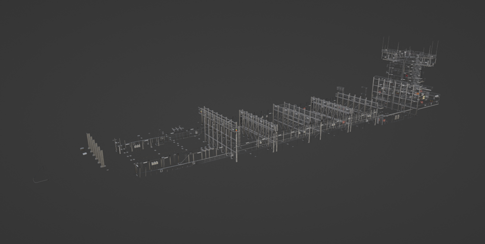
All ships were made by following pipeline: Making parent ship -> Making 4 body shapes -> Making 3 kinds of fillers -> Combining 4 Bodies and 3 fillers into 12 Variants - > Making LODs -> Tilting it as sinks variant and getting 12 more sinking versions.
In total we have 24 overload ship models.
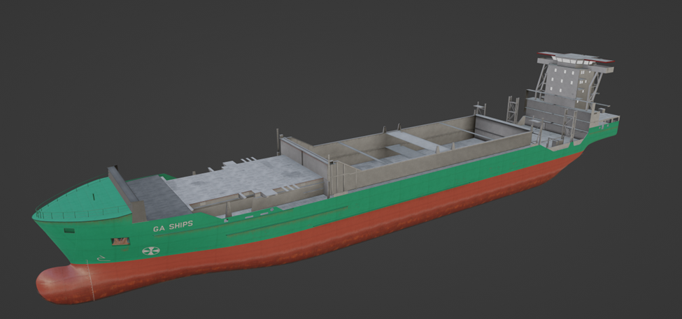
All 24 ship variants in reality are just 7 objects (4 bodies and 3 fillers), each ship is combination of 2 parts - body and filler. But 2 parts is not maximum we can split ship to, in reality there Is always part of ship which is the same for all these ships, like a part what each 24 variants have the same, also we can split interior, because for current LOD system it makes no sense, we can’t have LOD0 to LOD1 change on short distance – but we also can’t afford to have interior LOD0 to be alive for far distance, by this logic we can split interior too. See Splitting object practice example
Optimization of Blender source file
After splitting ship to modular parts and remaking the way how sinking version works (with the same modules just tilted according to empty point they referencing to) we came from 2 blend files with 3.6 GB weight (7.2 GB for normal and sink version) to one 39 MB file containing all 12 parts, it makes blend file work very smooth and in case of editing one part we fixing all ship variants easily.
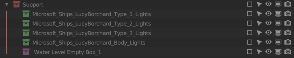
Blend file contains only modules and extra parts which these modules using (collision, environments occluder, lights erc).
LODs Optimization
New LOD system we have right now is tough but works well if artist understand what’s important and what’s not. Here I want to explain 2 important topics:
-
Rational instances – MSFS have specific pipelines, this is top-down simulator, objects are way different from other games like vehicles, weapons, characters. In MSFS we working with buildings or ships in this case which have structure and parts that used a lot of times in context of this object, we can call many small windows or air conditioners - modules, but we don’t have opportunity to place them ingame or with the same time efficiency like we doing it in blender, and also instance giving the same effect as module, they have same draw distance, polycount, drawcalls etc.
But at the same time if we have 500 windows, 200 ACs, 150 antennas we can’t keep them like that, it will increase a lor number of nodes for our object. What we can do is to remake them into rational instances.
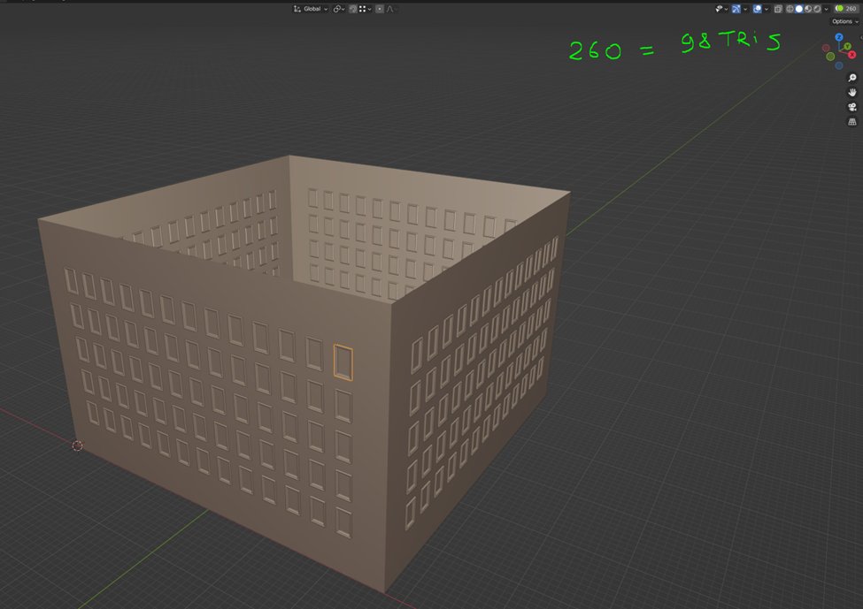
Here is an example, building have 260 same windows, windows have 98 Tris In context of that size building its not a big problem, but still there is ways to decrease number of objects and increase polycount not too much.
For example we can have window instance as column of 5 windows
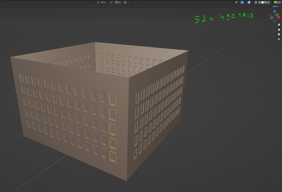
Or we can have line of windows as instance
As you can see we don’t increase polycount too much, usually a building of this size with all details costs ~25k tris and about 400 objects, and we can reduce the number of windows from 260 to 52 and we will add only 392 tris, in percent this difference will make more sense, we decreasing number of objects 2 times (from 400 to 192) but polycount increases only up to 1.6%
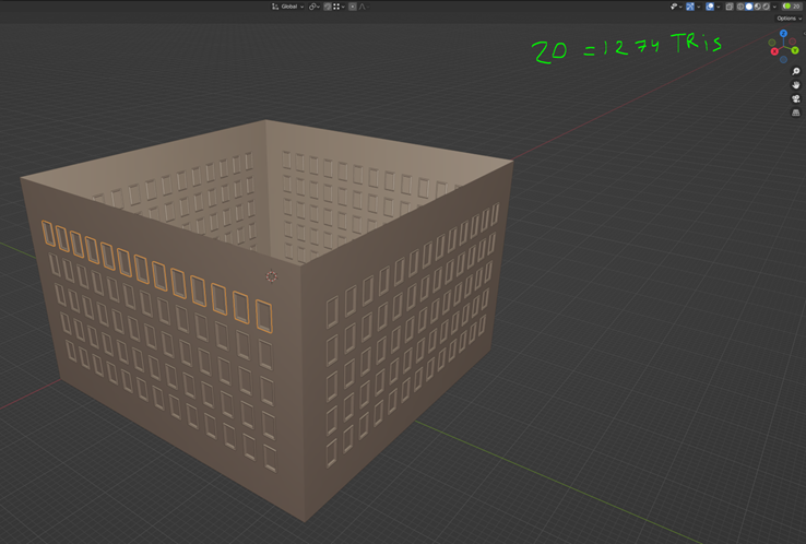
Biggest benefit of this method is, we can keep all instances in different “grouped instances” like on example bellow.
Summarizing I can tell working with instances in a context of one blenders scene gives a lot benefits and narrow control of node and polycount. -
80/20 method – Usually any object has bug surface (wall, roof, windows, some big assets) and they are taking 80-90% of surface but takes only 10-20% of polycount since its just surfaces, this percentage have big importance since when we zoom out this percentage becomes more dense, small details are dying by screen resolution and draw distance, also MSFS 2024 have very strong some kind of auto exposure, bright areas become more brighter and dark become darked, because of that smaller elements are losing any sense. So to make good LODs we need to keep our original 80-90% of surface with minimal changes, and because its just 10-20% of polycount it should be easier, most reduce will be on small details
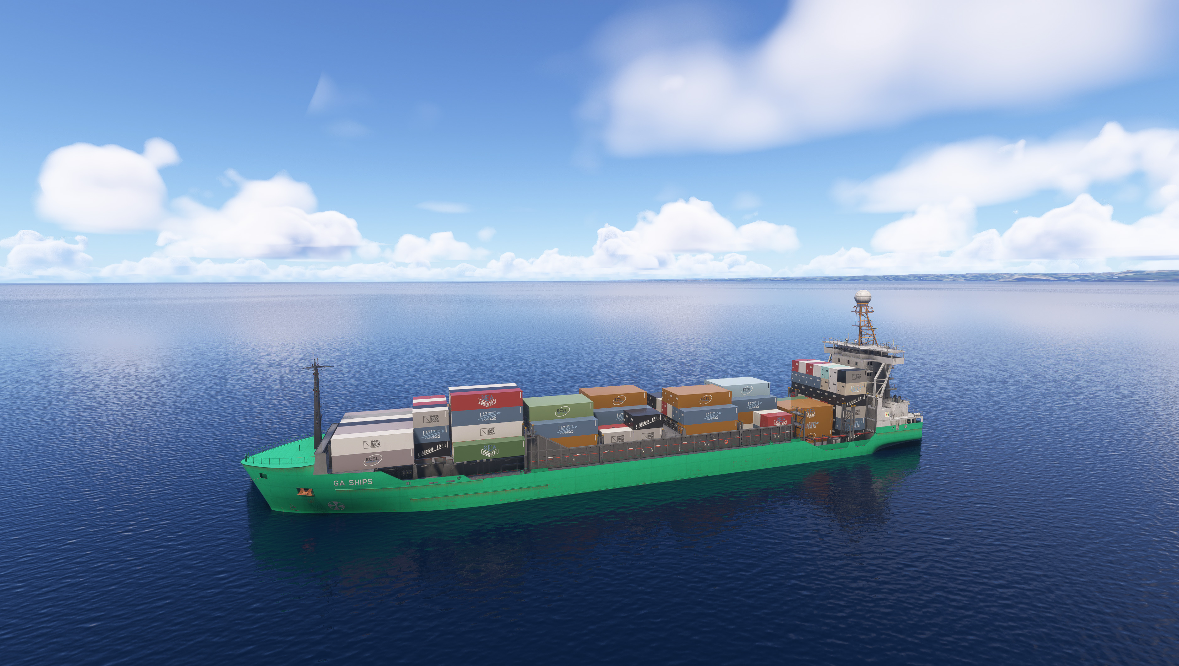
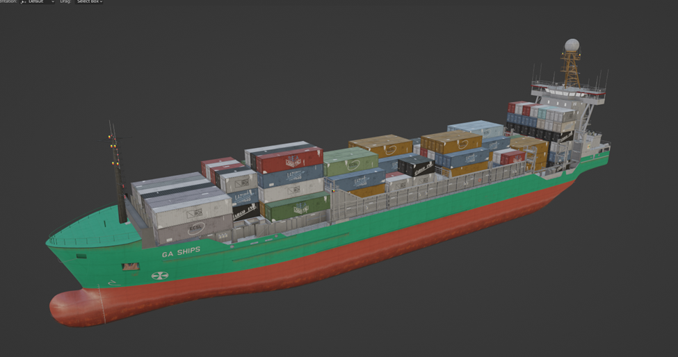
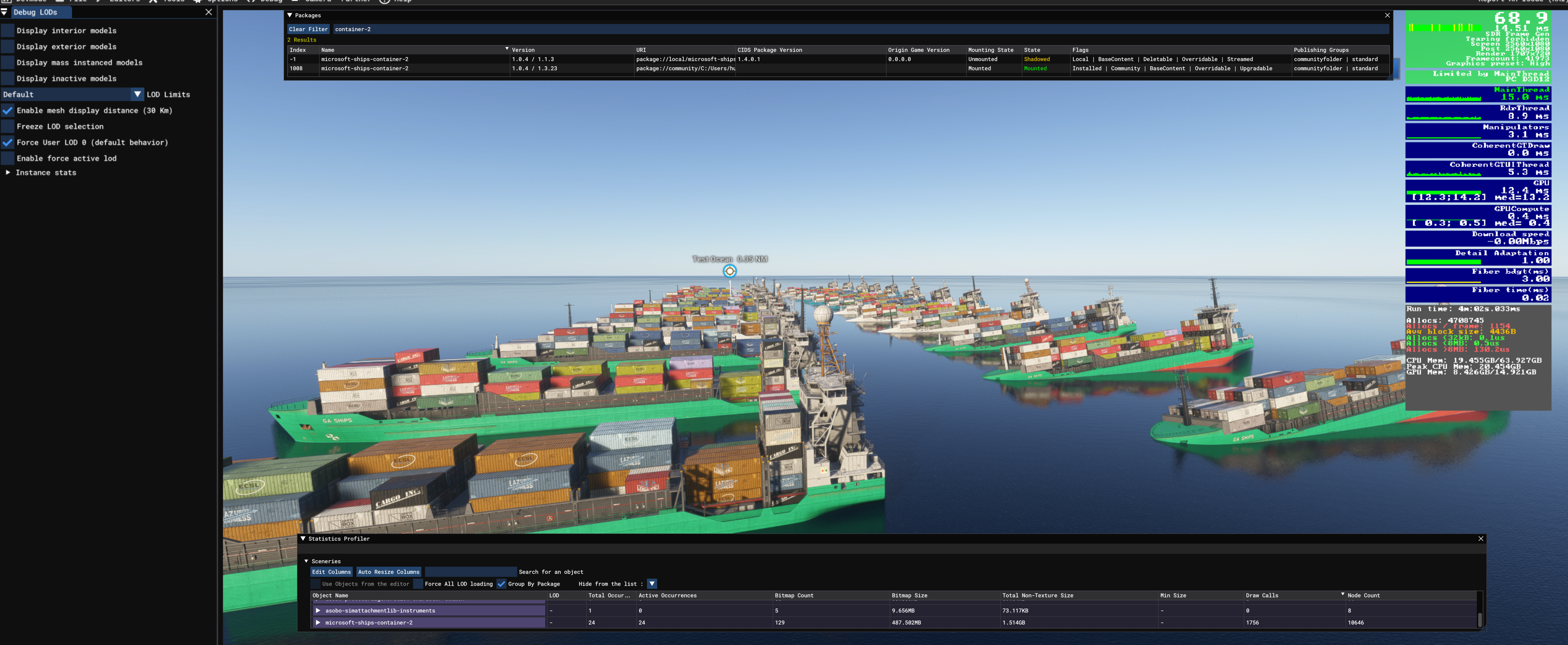
Test case- Microsoft_Ships_LucyBorchard
Comparative table between the old method and the new method:
| Aspect | OLD Structure | New Optimized Structure | Advantages of the New Structure |
|---|---|---|---|
| Draw Calls | 1756 | 272 | Significant reduction in draw calls improves GPU performance and reduces CPU-GPU communication overhead. |
| FPS Test PC 1 | 62 | 83 | PC: CPU: Ryzen 9 5900x, 64 GB Ram DDR 4, GPU: 4080 SUPER |
| FPS Test PC 2 | 28 | 64 | PC: CPU: Intel i7-11800H, 16 GB Ram DDR 4, GPU: RTX 3070 |
| Floating | Not floating properly, easily submerged by waves or remaining suspended in the air. | Floats better, more naturally, and no longer has the bug of floating in the air. | Due to the new system where the bounding box is no longer used, the boat's behavior in the water has been corrected and is now more natural and dynamic. |
| Total XML Files | 24 | 36 | Modularization allows better control and flexibility. |
| Total CFG Files | 28 | 28 | Consistent CFG structure maintained. |
| Average size | 2.61 GB | 97.3 MB | The very significant reduction in the average package size of approximately 95% is primarily due to the optimized approach adopted in the new modular asset structure. |
| Attachments Folder | Not present | Present with structured attachments | Easier organization, clarity, and reusability of assets. |
| Asset Management | Direct, no modular attachments | Modular, with clear attachment points | Easier updates, reduced complexity, and enhanced reusability. |
| LOD Management | Fixed, redundant LODs per model | Independent and modular LOD management | Improved runtime performance and better optimization. |
| Geometry Optimization | Redundant geometry across models | Optimized, shared geometry | Reduced memory footprint and improved loading times. |
| Texture Management | Embedded textures in multiple files | Externalized texture management | Drastic reduction in file size, easier texture management. |
| XML Structure | Flat, repetitive | Hierarchical with attachments | Easier troubleshooting, management, and scalability. |
| Sink Variation | Separate full models | Attached modular sink nodes and shared attachments | Significant reduction in package size by utilizing shared modular attachments between standard and variant (sink) models. This strategy eliminates redundancy, ensuring that common assets are stored only once and reused effectively across model sink variations. |
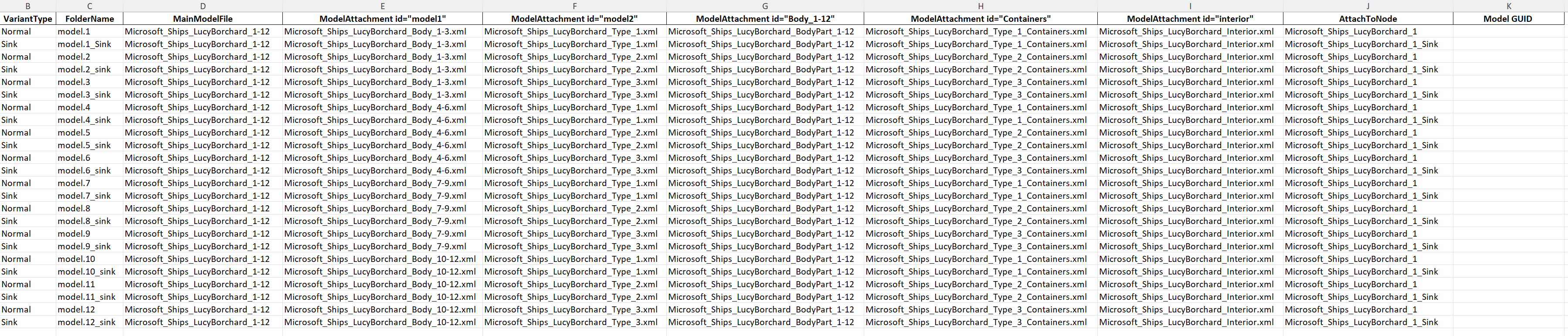
Model XML example
<?xml version="1.0" encoding="utf-8"?>
<ModelInfo guid="{5d86c58a-67a3-4356-bbbb-2e98d2a82199}" version="1.1">
    <LODS>
        <LOD minSize="0" ModelFile="../attachments/Microsoft_Ships_LucyBorchard_1-12.gltf">
            <AttachModel id="model1"/>
            <AttachModel id="model2"/>
            <AttachModel id="model3"/>
            <AttachModel id="model4"/>
            <AttachModel id="model5"/>
        </LOD>
    </LODS>
    <ModelAttachments>
        <ModelAttachment id="model1">
            <AttachToNode>Microsoft_Ships_LucyBorchard_1</AttachToNode>
            <Model>../attachments/Microsoft_Ships_LucyBorchard_Body_1-3.xml</Model>
        </ModelAttachment>
        <ModelAttachment id="model2">
            <AttachToNode>Microsoft_Ships_LucyBorchard_1</AttachToNode>
            <Model>../attachments/Microsoft_Ships_LucyBorchard_Type_1.xml</Model>
        </ModelAttachment>
        <ModelAttachment id="model3">
            <AttachToNode>Microsoft_Ships_LucyBorchard_1</AttachToNode>
            <Model>../attachments/Microsoft_Ships_LucyBorchard_BodyPart_1-12.xml</Model>
        </ModelAttachment>
        <ModelAttachment id="model4">
            <AttachToNode>Microsoft_Ships_LucyBorchard_1</AttachToNode>
            <Model>../attachments/Microsoft_Ships_LucyBorchard_Type_1_Containers.xml</Model>
        </ModelAttachment>
        <ModelAttachment id="model5">
            <AttachToNode>Microsoft_Ships_LucyBorchard_1</AttachToNode>
            <Model>../attachments/Microsoft_Ships_LucyBorchard_Interior.xml</Model>
        </ModelAttachment>
    </ModelAttachments>
</ModelInfo>
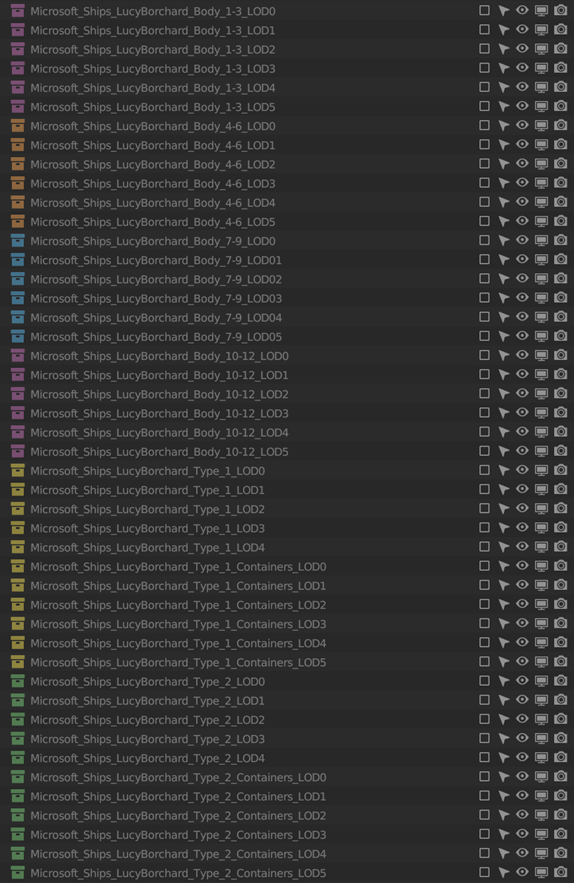
List of models in Microsoft_Ships_LucyBorchard
- Microsoft_Ships_LucyBorchard_1-12
- Microsoft_Ships_LucyBorchard_Body_1-3
- Microsoft_Ships_LucyBorchard_Body_4-6
- Microsoft_Ships_LucyBorchard_Body_7-9
- Microsoft_Ships_LucyBorchard_Body_10-12
- Microsoft_Ships_LucyBorchard_BodyPart_1-12
- Microsoft_Ships_LucyBorchard_Interior
- Microsoft_Ships_LucyBorchard_Type_1
- Microsoft_Ships_LucyBorchard_Type_1_Containers
- Microsoft_Ships_LucyBorchard_Type_2
- Microsoft_Ships_LucyBorchard_Type_2_Containers
- Microsoft_Ships_LucyBorchard_Type_3
- Microsoft_Ships_LucyBorchard_Type_3_Containers
Ships variants
Splitting object practice example
One of 4 body variants
One of 3 filler types
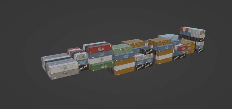
One of 3 container types we have (for better variability and option to remove it so ship will be without containers)
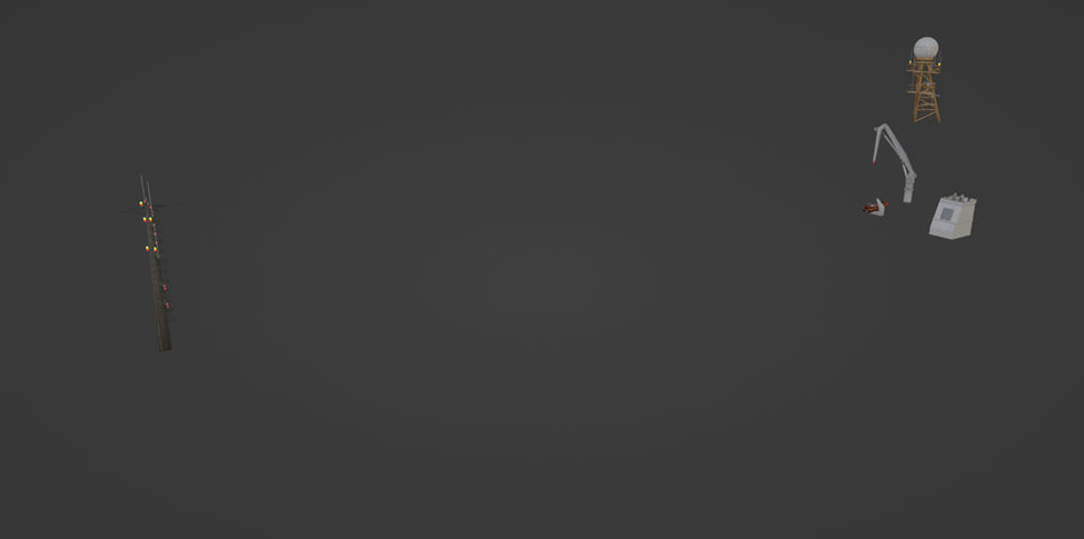
Repetitive part that used in all 12 ship variants
Interior part that used in all 12 ship variants

Dev package structure
─microsoft-ships-container-2
    ├───PackageDefinitions
    │   └───microsoft-ships-container-2
    │       └───ContentInfo
    ├───PackageSources
    │   └───SimObjects
    │       └───Boats
    │           ├───Microsoft_Ships_LucyBorchard
    │           │   ├───attachments
    │           │   ├───model.1
    │           │   ├───model.10
    │           │   ├───model.11
    │           │   ├───model.12
    │           │   ├───model.2
    │           │   ├───model.3
    │           │   ├───model.4
    │           │   ├───model.5
    │           │   ├───model.6
    │           │   ├───model.7
    │           │   ├───model.8
    │           │   ├───model.9
    │           │   └───texture
    │           └───Microsoft_Ships_LucyBorchard_Sink
    │               ├───model.10_Sink
    │               ├───model.11_Sink
    │               ├───model.12_Sink
    │               ├───model.1_Sink
    │               ├───model.2_Sink
    │               ├───model.3_Sink
    │               ├───model.4_Sink
    │               ├───model.5_Sink
    │               ├───model.6_Sink
    │               ├───model.7_Sink
    │               ├───model.8_Sink
    │               ├───model.9_Sink
    │               └───texture
    └───WORK
In game compare
Performance
Version 1.1.0 | FPS- 84.3 | Draw calls- 219
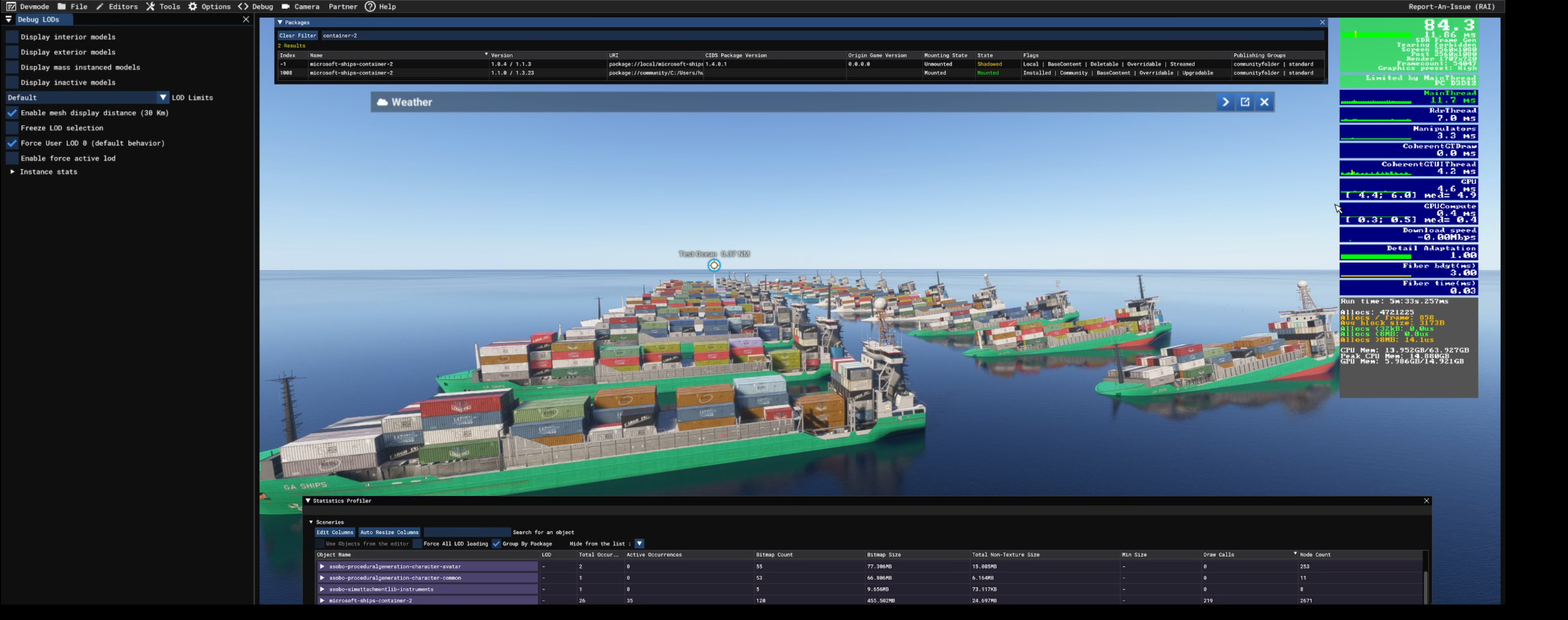
Version 1.0.4 | FPS- 68.9 | Draw calls- 1756
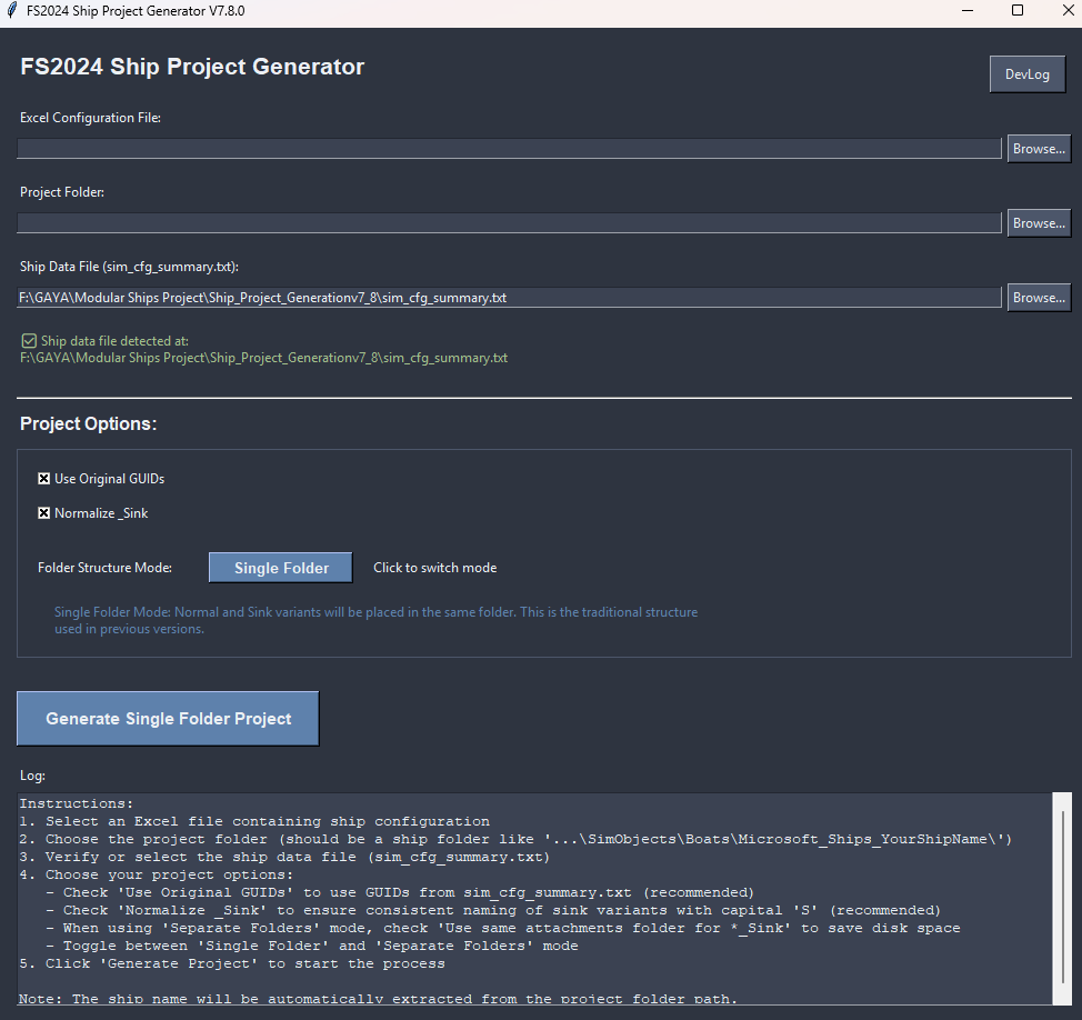
Ship Project Generation Script
This script is designed to automate the setup of modular ship folders and configurations for one boat at time. (The package definition is updated with all boats in the folder.) Here's a breakdown of what it does:
-
Folder Selection & Ship Name Detection
- The user selects a boat folder.
- The script automatically detects the ship name based on the folder name, attachments folder and other files if exists following a standardized naming convention.
-
Project Status Analysis
- It checks whether a PackageDefinition.xml already exists for the selected ship.
- Extracts current package and dependency versions.
- Detects whether the selected ship is already included in the definition and whether it's a regular or _Sink model.
-
Attachments & Excel Mapping
- Upon clicking Generate, it reads all attachment XMLs from the
/attachments/folder. - It then matches attachment nodes and definitions based on an Excel file filled out by the artist.
- Upon clicking Generate, it reads all attachment XMLs from the
-
Database Cross-Referencing
- It cross-checks data with a local
sim_cfg_summary.txtdatabase to retrieve pre-defined configurations and GUIDs. - If Use Original GUIDs is checked:
- It tries to fetch the GUID from the sim config summary.
- If unchecked:
- It prioritizes GUIDs from Excel, then the database, and if none found, generates a new one.
- It cross-checks data with a local
-
Automatic Folder & File Generation
- Creates folders like model.X and model.X_Sink as needed.
- Each model includes:
model.cfgaircraft.X.xmloraircraft.X_Sink.xml- Correct attachment paths and ship config structure as defined by internal rules.
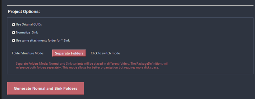
- Optional behavior:
- Normalizes
_Sinknaming. - Merges attachments from the main model into the Sink variant (if toggled).
- Creates separated or unified folders depending on the chosen mode.
- Normalizes
-
Final Integration
- Updates or generates the PackageDefinition.xml with all valid models found in the /boat/ folder.
- Applies custom or default version numbers.
- Clearly logs all steps, errors, and success messages in a rich, color-coded UI.